Vcr cascaded Schematic diagram of a simple vcrs. 1: an idealized, single-stage vcr system.
T-S Diagram of VCR cycle | Download Scientific Diagram
-process operation of a vcr system [6] What is vcr? Vcr current detailed linearized
T-s diagram of vcr cycle
Compression vapour schematic vcr vapor2: two-stage cascaded vcr system developed in the study. Schematic layout of the cascade vcr systemSchematic representation of the modifications introduced in the vcr 2/1.
National vcr day. dust it offFlow diagram of vcr system (a) detailed schematic diagram of the vcr current source. (bRefrigeration schematic diagram.

Refrigeration compression vapor function conditioning absorption explained
Simple vapour compression refrigeration cycle on p-h diagramVcr refrigeration Vapor compression systemSchematic diagram of experimental vcr system..
How a vcr works2: main components of vcr cycle [37]. Schematic diagram of vcr with instrumentations.Vcr diagram.

-process operation of a vcr system [6]
Refrigeration control circuit diagram(a) vcr simple cycle; (b) vcr cycle with internal power regeneration 2: main components of vcr cycle [37].Vcr modelling freshwater assisted framework generate.
Schematic diagram of a two-stage vcr system.Compression refrigeration vapor refrigerator vapour evaporator expansion condenser timetoast Simple vapour compression systemSimple vapour compression refrigeration system.

P-h diagram of vcr cycle
How vapor compression refrigeration system worksSchematic diagram of a proposed vcr system Figure f.4 schematic of a vcr system with a counter-flow heat exchangerFlow diagram of vcr system.
Schematic diagram of a simple vcrs.Schematic diagram of experimental vcr system. .


Schematic diagram of a simple VCRS. | Download Scientific Diagram

T-S Diagram of VCR cycle | Download Scientific Diagram

(a) Detailed schematic diagram of the VCR current source. (b

schematic diagram of experimental VCR system. | Download Scientific Diagram

Figure F.4 Schematic of a VCR system with a counter-flow heat exchanger

(a) VCR simple cycle; (b) VCR cycle with internal power regeneration
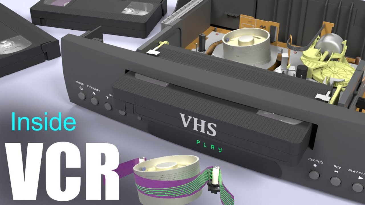
How a VCR Works
![2: Main components of VCR cycle [37]. | Download Scientific Diagram](https://i2.wp.com/www.researchgate.net/profile/Dia_Milani/publication/280082882/figure/download/fig4/AS:669077525770240@1536531921022/Main-components-of-VCR-cycle-37.jpg)
2: Main components of VCR cycle [37]. | Download Scientific Diagram
